[Lab 3] Multiple JTAG UART

[Lab 3] Multiple JTAG UART

par Amaury Pierre Jiezhi Wei,
Number of replies: 6

Hello,

I have a question regarding Lab 3. The focus is on serial communication between the PC and the two Nios-II processors.

I read in details the Multiprocessor design example from Intel/Altera at the link given on the Moodle page (Intel Link to tutorial). I noticed that they have multiple JTAG UART instanced on the same USB cable (they have 6 instances running on Fig 1-11 p.35/44 in the tutorial) and they can all output data at the same time.

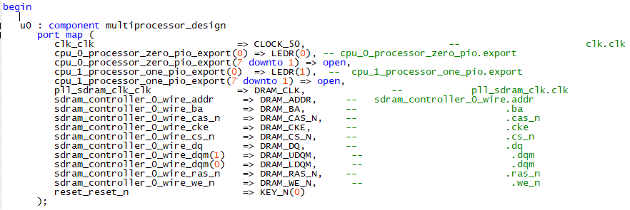
In the Lab 3 instructions, we are asked to use a JTAG UART (cpu_0) and an UART component cpu_1). However, I didn't find to which pins to connect the two serial wires UART_TX and UART_RX in the FPGA part (there are two UART pins in the De1_SoC_top_level.vhd but they are connected to the HPS side of the board).

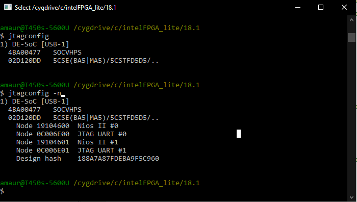
To fix this, I tried using two JTAG UART (one per cpu). Using the Nios-II terminal, I can see both JTAG UART interfaces and connect to both of them at the same time (cf. figure below). When I start the processors one by one, I can see the outputs of the first processor in one terminal, but as soon as I start the second, the first terminal stops updating and I don't receive any more outputs.

Does anyone know how to fix this? If not, how can I connect the UART module to one of the USB ports on the board?

Thanks a lot.

Amaury


nios2-terminal

In reply to Amaury Pierre Jiezhi Wei

Re: [Lab 3] Multiple JTAG UART

par Sahand Kashani-Akhavan,

This is a good question. I recall when I did this lab I used the JTAG UART for one CPU and a standard UART for another CPU. Regarding the standard UART, I had exported the TX and RX signals to two GPIO pins then used a UART-to-usb adapter which was in the lab to connect these pins to the host machine. I was using putty back then on windows and you could tell it to read from a serial port that was being emulated by the usb adapter.

As far as I recall, there were only a few such USB adapters in the lab and we were passing them around with the other groups.

I looked a bit deeper into that tutorial and they use the "--instance" argument to nios2-terminal to select which CPU subsystem to download the code to (in your screenshot you are just listing instances, not choosing which one to run programs on). Are you also using this --instance argument?

Other than that I don't have more hands-on experience with multiple JTAG UARTs...

In reply to Sahand Kashani-Akhavan

Re: [Lab 3] Multiple JTAG UART

par Amaury Pierre Jiezhi Wei,

Thank you for your answer.

I see, unfortunately I don't have such an adapter. Yes I used the --instance argument with 0 and 1 to connect to the different CPUs, but still no success.

I guess I will just switch from one CPU to another by activating/deactivating one JTAG-UART at a time.

In reply to Amaury Pierre Jiezhi Wei

Re: [Lab 3] Multiple JTAG UART

par Sahand Kashani-Akhavan,

By the way, if your goal is just to determine which CPU is holding the object you're guarding concurrent access to, you could always just have each CPU flip a bit on a GPIO port and see this with a logic analyzer. One can get creative :)

In reply to Sahand Kashani-Akhavan

Re: [Lab 3] Multiple JTAG UART

par Amaury Pierre Jiezhi Wei,
That's a good idea, thanks for the tip!

Actually I think I found another problem I didn't realize before. In the first place, I was just printing in the terminal, and I assumed that the lack of messages from one CPU was due to the JTAG-UART. However, it seems that when I run the 2nd CPU, the first one stops.

I came to this conclusion as I tried to implement your idea with LEDs. Every 500ms, an LED is set or cleared by one of the CPUs. Each CPU has its own LED. When I run cpu_0, the LED 0 demonstrates an alternating pattern. However, when I start the cpu_1 (connected to LED 1), the LED 1 alternated byt the first one seems to stop. Indeed, the LED 0 stays set all the time. Please see the video below (3.3 MB) for an example.


That would explain why the prints on the JTAG-UART stops.

Here is my top_level component and my Qsys system for the cpu_0 (it's the same for cpu_1).

top_level

qsys_cpu_0

Do you have an idea of what is happening here? Thanks for the help.
In reply to Amaury Pierre Jiezhi Wei

Re: [Lab 3] Multiple JTAG UART

par Sahand Kashani-Akhavan,

I can't tell for sure, but I think  both your CPUs are using the same memory for their code segment, and hence when you start the 2nd processor, the memory contents get overwritten and the first processor stops.

I think this is the case as your top-level VHDL file has the SDRAM-related pins, but I don't see the SDRAM controller in your Qsys file as you only showed the CPU_0 subsystem. Though you have an on-chip memory in there, I see you have also exported the instruction_master port of the CPU through the mm_bridge_0 component (instead of just exporting the data_master port). If this port is indeed connected to the SDRAM controller on the outside, and it is being done by both CPU subsystems, then I suspect that the linker is placing both CPU's executable code in the same SDRAM segment (the tools by default choose the largest memory connected to the instruction_master port for code & data, and in your case that's the SDRAM).

Try to only export the data_master port through the mm_bridge component in both subsystems, then check again. Hopefully that should solve the issue.

In reply to Sahand Kashani-Akhavan

Re: [Lab 3] Multiple JTAG UART

par Amaury Pierre Jiezhi Wei,

Thanks for you answer. Indeed it was a memory problem. I removed the instruction connection from the Master bridge, but then the processors were not starting anymore. The Nios-II eclipse was not downloading the code on the two separate memories, but on the SDRAM.

A TA helped me fix the problem by modifying the BSP (cf. image). The memory targets were not selected properly (I thought they would when compiling with Quartus).

Now I can have the 2 JTAG-UART connected at the same time and receive information from the 2 CPUs.

bsp-fix

bsp-fix1