I2C troubleshoot

I2C troubleshoot

by Jon Märki -
Number of replies: 11

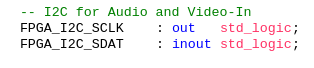
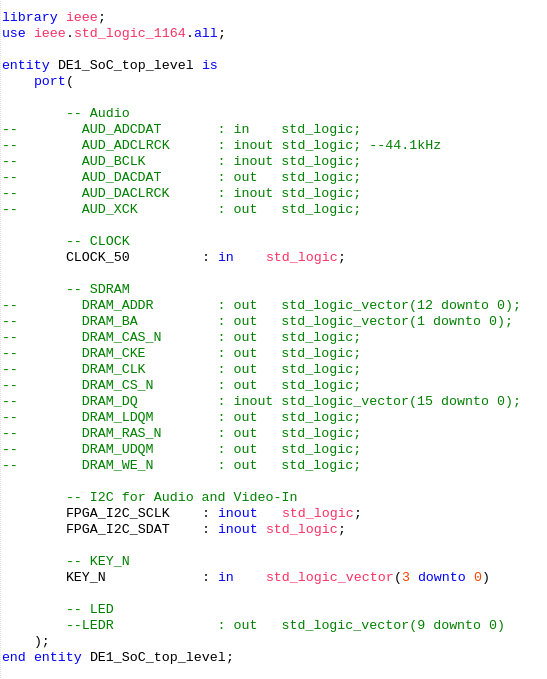
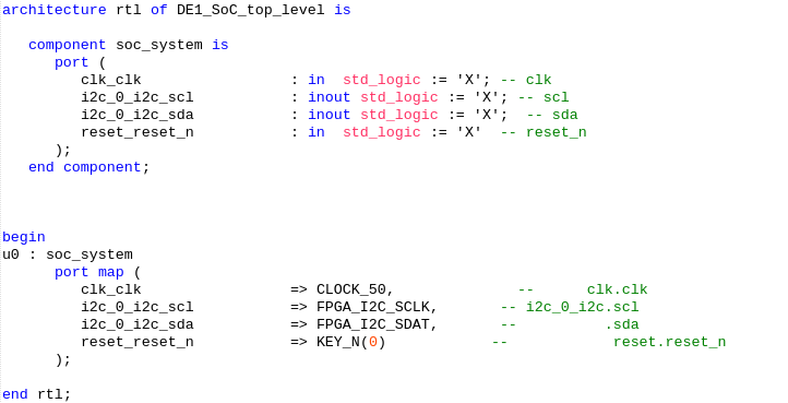
Hello, I am currently trying to setup a chip using the I2C IP component from qsys. It doesn't work (timeout error) but I don't really know how can I check what the problem is. I could spend my afternoon in debug mode and check what's the matter but I suspect my wiring to be wrong as I don't really understand why the IP component has an Opendrain enable and an input for each the clock and how to wire it as there are only two I2C lines for the audio components. 

Any help would be greatly appreciated !

Thank you

Jon

In reply to Jon Märki

Re: I2C troubleshoot

by Sahand Kashani-Akhavan -

Honestly, I've never used the I2C core from qsys. I know it's the same one as on opencores with an Avalon wrapper, but that core was a mess and I never understood how to use it.

I uploaded the I2C core that we gave the students of last semester's Embedded Systems course on moodle.
https://moodlearchive.epfl.ch/2019-2020/mod/resource/view.php?id=1077994

You can try this one out as we know it works. There's a demo and a readme in the archive to explain how to use it.

In reply to Sahand Kashani-Akhavan

Re: I2C troubleshoot

by Jon Märki -

Hey thank you very much for your reply. So I set it up but it doesn't work either (I've got a "Bad acknowledge" according to the code). There was one thing I did that may have changed something: The clock in this design is inout and the clock wire from the top level entity is out only so I changed the inout into an out type. Otherwise I use the functions of the demo and I can't configure my audio chip... 

Thank you for your help

In reply to Jon Märki

Re: I2C troubleshoot

by Sahand Kashani-Akhavan -

Could you tell us what FPGA pins you are connecting your I2C controller to? It seems like you are not receiving any response on the other side.

Note that the clock should remain as an inout port  as both an I2C master and slave can modify this signal (slaves can hold the bus to slow down a master).

I used this I2C controller for an audio project when I was taking the course and had the following high-level connections. Basically the I2C controller should be connected to the FPGA_I2C_SCLK and FPGA_I2C_SDAT ports. Are you using the same ones?


In reply to Sahand Kashani-Akhavan

Re: I2C troubleshoot

by Jon Märki -

Indeed I changed the IP component pin to be out only. I had this configuration and I was kinda scared to change it as I was thinking this is the definitive way the board is wired so we couldn't change it. Now I changed it and I'll keep you updated on how it goes. 


In reply to Sahand Kashani-Akhavan

Re: I2C troubleshoot

by Jon Märki -

So it still doesn't work. I still have a communication error...

In reply to Jon Märki

Re: I2C troubleshoot

by Sahand Kashani-Akhavan -

It's difficult to say what's wrong without more info. Please upload a drawing of your full system and the top-level vhdl file so we can see how things are wired. Also, what frequency is your I2C SCLK line running at?

In the meantime, I'd recommend you plug a logic analyzer on those SCLK and SDAT lines to see what the hardware is doing.

In reply to Sahand Kashani-Akhavan

Re: I2C troubleshoot

by Jon Märki -

Yes my apologies, I had to do something else this morning so I thought I would just quickly update what I did, now I have the time to work on it so here you have my qsys and my toplevel as well as my code, maybe you can find what I did wrong. I will indeed check what happens on the wires with the the signal tap logic analyzer from quartus.


Top level entity:


Top level ports:


And the C code:


I notice that I haven't mentionned that I changed the TRDB_D5M_I2C_ADRESS. In my thinking it is supposed to be the adress of the device we want to communicate with isn't it ? If so, I set it to the adress found in the DE1-SoC SchematicFile available in the course. Before, the adress was 0xba and it did not cause any error. As you can see I set the clock to be 50MHz which may be too fast aswell but I couldn't justify putting something else so I though this would make sense.

Thank you for your precious time.

Jon

In reply to Jon Märki

Re: I2C troubleshoot

by Sahand Kashani-Akhavan -

Yes, using 0x34 as specified in the schematic is correct for the I2C address of the WM8731. Also, you are not driving the I2C clock at 50 MHz, but rather you are setting a clock divider internally such that the I2C clk is around 100 MHz (check the code inside i2c_inst to see how this works).

I think the problem you're having is that you are not driving AUD_BCLK, and so the WM8731 is basically unclocked and is a zombie. Try plugging in a clock at the correct frequency needed over here and then re-check that the I2C controller receives a response.

In reply to Sahand Kashani-Akhavan

Re: I2C troubleshoot

by Jon Märki -

Well the problem is that for the next step, BCLK is going to be "in" because the chip is going to be set in master mode. This clock will be generated from the internal clock of the chip so I wouldn't wire my clock as an output to this. What I want to do is first check my I2C connection by using the analog bypass methods just to check if everything is okay and then work my way up to the project.

The internal clock is necessary to have a coherent behaviour according to the sampling frequency because if I use the 50MHz clock, I don't have a good multiplier between 44.1KHz and 50MHz which would cause me to skip some samples and have to calculate when to do it so no samples would be a combination of two actual samples. 

In the schematic you can see the internal clock that is highlighted and the path of the mic that I want to make using the correct I2C messages.


In reply to Jon Märki

Re: I2C troubleshoot

by Sahand Kashani-Akhavan -

You're right. Sorry, it was late last night and I made a mistake. I meant to say that you should provide a clock to the device's master clock, AUD_CLK, before trying to test I2C communication.

In reply to Sahand Kashani-Akhavan

Re: I2C troubleshoot

by Jon Märki -

Running the signal tap logic analyzer from Quartus, there are no signals that change. Nothing happens... 

Here you have the signals I have watched :